Active Cables
As data center connections double in bandwidth with every generation, active cables will become more prevalent if not dominant for short reach connections. There are two types of active cables: Active Electrical Cables (AECs), sometimes called Active Copper Cables (ACCs), and Active Optical Cables (AOCs). Both types have pluggable transceivers permanently tethered together with multiple strands of copper or fiber cable. All pluggable transceivers, whether copper or optical, operate using an industry-standard 3.3V supply from which they must derive the power rails needed internally. Depending on the semiconductor technology deployed, this may be just a few rails or as many as eight to ten.
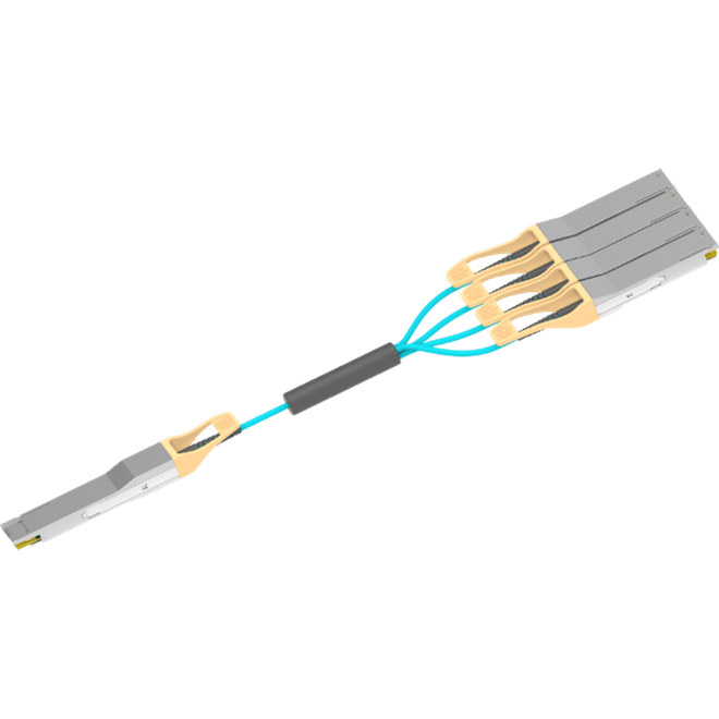
Typically, fewer power rails are needed to implement an AEC than an AOC and there is at least one AEC merchant silicon vendor whose IC requires just one rail – 3.3V. Because of this simplicity, we will focus on AOCs, whose power demands are more complicated.
AOCs are typically architected from the same silicon building blocks as regular optical transceivers in that they need lasers, laser drivers, TIAs (Transimpedance Amplifiers), and CDRs (Clock and Data Recovery). As AOCs are, by definition, short reach, VCSEL lasers are the lasers of choice. High-performance 400G transceivers may also need additional components such as DSPs.
In architecting a 400G AOC, one could either optically choose four lanes of 100G or eight lanes of 50G. Since 50G lanes are the older, more mature technology, the cost for 50G lanes will be less than 100G lanes, so most 400G cables will initially use an 8x50G configuration. The IEEE has standardized the eight lanes of 50G and named it 400GBASE-SR, or 400G-SR8 for short. While the standard doesn’t apply to AOCs, the same silicon is largely used to design both transceivers and AOCs. And there’s at least one chipset that doesn’t use a DSP. Such an implementation might use the following power rails.
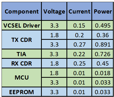
Table 1: non-DSP AOC Power Rails
In this example, we’re only dealing with two voltages: 1.8V or the input source 3.3V. The power can be provided for this architecture with a single 1.8V 1A buck converter and we can use a 3.3V input Empower IVR to generate this rail.
A DSP implementation will have a more complex power tree. CMOS DSPs typically require a few power supplies: core digital, digital I/O, and one or two analog power rails as shown in Table 2.
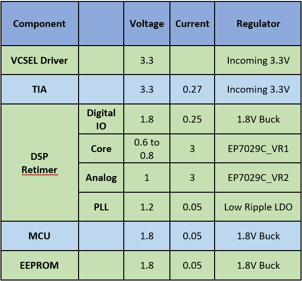
Table 2: DSP-Based Power Rails
A traditional approach to creating the power rails in Table 2 would be to use discrete buck converters. A solution based on that approach is proposed in Figure 1.
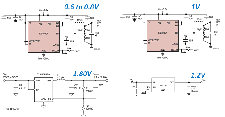
Figure 1: Discrete Converters to Address Power Rails in Table 2
This approach is utilitarian – it gets the job done but it takes 45 components and roughly 360mm2 of PCB space and gives a system efficiency of 88%. Figure 2 shows an alternate implementation using an Empower IVR.
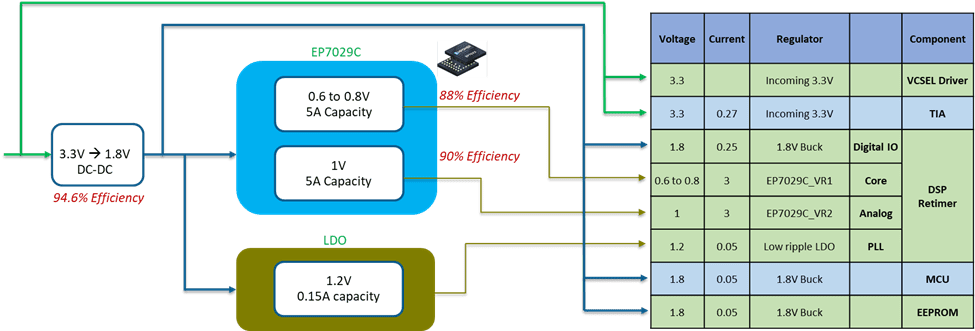
Figure 2: Empower IVR to Address Table 2 Power Rails
With the Empower approach, the goal is to reduce the component count and board footprint. The EP7029C shown handles the core and analog rails of the DSP. In order to feed the EP7029C, the 1.8V rail is oversized so that it can bias the IC and still power the other loads. The goal of footprint and BOM reduction is achieved by the Empower approach as the overall number of components shrinks to just 15 and the PCB area comes in at a compact 155mm2. System efficiency is still a respectable 85%, which is the best achievable given a 3x reduction in components and 2x reduction in area. Figure 3 shows the Implementation of this circuit.
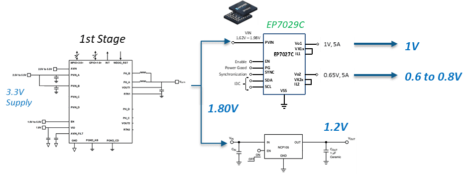
Figure 3: Empower IVR circuit to implement Table 2 Power Rails
With designers continually being asked to pack more functionality into less space, power supply designs are being squeezed like never before. While traditional buck regulator technology trades size for efficiency, Empower IVRs can avoid this compromise by offering the best of both worlds.